MPLS is a simple protocol for me. But some of my colleagues in the discussion asked me to talk about it in more detail.
Terminology
LSR (Label Switch Router) -- Any router that pushes labels onto packets, pops labels from packets, or
simply forwards labeled packets.
CE -- Customer edge
simply forwards labeled packets.
CE -- Customer edge
PE -- Provider edge
E-LSR (Edge LSR) -- An LSR at the edge of the MPLS network, meaning that this router
processes both labeled and unlabeled packets.
Ingress E-LSR -- For a particular packet, the router that receives an unlabeled packet and then
inserts a label stack in front of the IP header.
Egress E-LSR -- For a particular packet, the router that receives a labeled packet and then
removes all MPLS labels, forwarding an unlabeled packet.
ATM-LSR -- An LSR that runs MPLS protocols in the control plane to set up ATM
virtual circuits. Forwards labeled packets as ATM cells.
ATM E-LSR -- An E-edge LSR that also performs the ATM Segmentation and Reassembly
(SAR) function.
TE -- Traffic Engineering
CEF -- Cisco Express Forwarding
RIB -- Routing Information Base
FIB -- Forwarding Information Base
LFIB -- Label Forwarding Information Base
LFIB -- Label Forwarding Information Base
LIB -- Label Information Base. LSRs store labels and related information inside. The LIB essentially
holds all the labels and associated information that could possibly be used to forward packets.
holds all the labels and associated information that could possibly be used to forward packets.
MPLS unicast IP
MPLS requires the use of control plane protocols (for example, OSPF and LDP) to learn labels,correlate those labels to particular destination prefixes, and build the correct forwarding tables.

FORWARDING PLANE
CEF Review
CEF Review

MPLS Unicast IP Forwarding Concept
The MPLS forwarding paradigm assumes that hosts generate packets without an MPLS label;then, some router imposes an MPLS label, other routers forward the packet based on that label,
and then other routers remove the label. The end result is that the host computers have no
awareness of the existence of MPLS.

FIB —Used for incoming unlabeled packets. Cisco IOS matches the packet’s destination IP
address to the best prefix in the FIB and forwards the packet based on that entry.
LFIB —Used for incoming labeled packets. Cisco IOS compares the label in the incoming
packet to the LFIB’s list of labels and forwards the packet based on that LFIB entry.
MPLS Header

MPLS TTL Propagation On/Off


CONTROL PLANE
LDP Concept
For each route in the routing table, find the corresponding label information in the LIB,based on the outgoing interface and next-hop router listed in the route. Add the
corresponding label information to the FIB and LFIB.
The first section of command enable MPLS globally
ip cef

mpls ip

mpls label protocol ldp
The second section is <b> config file
If everything is configured correctly, the neighborhood will be enabledPE1(config)#do sh run ! ! interface Loopback1 ip address 1.1.1.1 255.255.255.255 ! interface FastEthernet1/0 ip address 192.168.12.1 255.255.255.0 duplex auto speed auto mpls ip ! interface FastEthernet1/1 ip address 192.168.14.1 255.255.255.0 duplex auto speed auto mpls ip ! interface FastEthernet2/0 ip address 192.168.15.1 255.255.255.0 duplex auto speed auto ! ! router eigrp 1 network 1.1.1.1 0.0.0.0 network 192.168.12.0 network 192.168.14.0 network 192.168.15.0 ! mpls ldp router-id Loopback1 !

* %LDP-5-NBRCHG: LDP Neighbor 2.2.2.2:0 (1) is UP
| LDP Reference | LDP Feature LDP Implementation |
| Transport protocols | UDP (Hellos), TCP (updates) |
| Port numbers | 646 (LDP), 711 (TDP) |
| Hello destination address | 224.0.0.2 |
| Who initiates TCP connection | Highest LDP ID |
| TCP connection uses this address | Transport IP address (if configured), or LDP ID if no transport address is configured |
| LDP ID determined by these rules, in order or precedence | Configuration Highest IP address of an up/up loopback when LDP comes up Highest IP address of an up/up non-loopback when LDPcomes up |
And if you can "ping" to see mpls-header

Okay, now look at process to determine the Outgoing Label

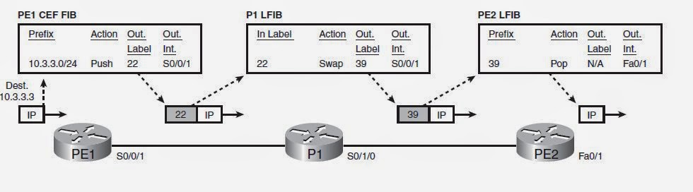
FIB aтв LFIB examples


MPLS VPNs

MPLS VPN Control Plane concept


Key: Duplicate Customers Address range
MPLS VPN Data Plane
PEs have several other duties as well, all geared toward the issue of learning customer routes and
keeping track of which routes belong to which customers. PEs exchange routes with the connected
CE routers from various customers, using either EBGP, RIP-2, OSPF, or EIGRP, noting which
routes are learned from which customers. To keep track of the possibly overlapping prefixes, PE
routers do not put the routes in the normal IP routing table—instead, PEs store those routes in
separate per-customer routing tables, called VRFs. Then the PEs use IBGP to exchange these
customer routes with other PEs—never advertising the routes to the P routers.
An outer MPLS header (S-bit = 0), with a label value that causes the packet to be label
switched to the egress PE
An inner MPLS header (S-bit = 1), with a label that identifies the egress VRF on which to base
the forwarding decision
switched to the egress PE
An inner MPLS header (S-bit = 1), with a label that identifies the egress VRF on which to base
the forwarding decision
MPLS VPN Data Plane concept
MPLS VPN Control Plane concept
VRFs
VRF components:
1) An IP routing table (RIB)
2) A CEF FIB, populated based on that VRF’s RIB
3) A separate instance or process of the routing
2) A CEF FIB, populated based on that VRF’s RIB
3) A separate instance or process of the routing
Route Distinguishers (RDs)
MPLS deals with the overlapping prefix problem by adding another number in front of the original
BGP NLRI (Network Layer Reachability Information) (prefix). Each different number can represent a different customer, making the NLRI values unique.
BGP NLRI (Network Layer Reachability Information) (prefix). Each different number can represent a different customer, making the NLRI values unique.
To do this, MPLS took advantage of a BGP RFC, called MP-BGP (RFC 4760), which allows for the re-definition of the NLRI field in BGP Updates. This re-definition allows for an additional variable-length number, called an address family, to be added in front of the prefix.
MPLS RFC 4364, “BGP/MPLS IP Virtual Private Networks (VPNs),” defines a specific new
address family to support IPv4 MPLS VPNs—namely, an MP-BGP address family called Route
Distinguishers (RDs).
RDs allow BGP to advertise and distinguish between duplicate IPv4 prefixes. The concept is
simple: advertise each NLRI (prefix) as the traditional IPv4 prefix, but add another number (the
RD) that uniquely identifies the route.
In particular, the new NLRI format, called VPN-V4, has the following two parts:
> 64-bit RD
> 32-bit IPv4 prefix
> 64-bit RD
> 32-bit IPv4 prefix
RD composition
> 2-byte-integer:4-byte-integer
> 4-byte-integer:2-byte-integer
> 4-byte-dotted-decimal:2-byte-integer
> 4-byte-dotted-decimal:2-byte-integer
In all three cases, the first value (before the colon) should be either an ASN or an IPv4 address.
The second value, after the colon, can be any value you wish. For example, you might choose an
RD that lists an LSR’s BGP ID using the third format, like 3.3.3.3:100, or you may use the BGP
ASN, for example, 432:1.
The second value, after the colon, can be any value you wish. For example, you might choose an
RD that lists an LSR’s BGP ID using the third format, like 3.3.3.3:100, or you may use the BGP
ASN, for example, 432:1.
Route Targets (RTs)
MPLS uses Route Targets to determine into which VRFs a PE places IBGP-learned
routes.
routes.
MPLS VPN CONFIGURATION

1. Creating each VRF, RD, and RT, plus associating the customer-facing PE interfaces with the correct VRF
a) Components:
VRF Cust-A, RD 1:111, RT 1:100
VRF Cust-B, RD 2:222, RT 2:200
b) Concepts:
Configuring the VRF with the ip vrf vrf-name command
Configuring the RD with the rd rd-value VRF subcommand
Configuring the RT with the rt {import|export} rt-value VRF subcommand
Associating an interface with the VRF using the ip vrf forwarding vrf-name interface subcommand
Configuration on PE1
Configuration on PE2ip vrf Cust-A rd 1:111 route-target import 1:100 route-target export 1:100 ip vrf Cust-B rd 2:222 route-target import 2:200 route-target export 2:200 interface fastethernet2/0 ip vrf forwarding Cust-A ip address 192.168.15.1 255.255.255.0 no shutdown interface fastethernet2/1 ip vrf forwarding Cust-B ip address 192.168.16.1 255.255.255.0 no shutdown
2. Configuring the IGP between PE and CEip vrf Cust-A rd 1:111 route-target import 1:100 route-target export 1:100 ip vrf Cust-B rd 2:222 route-target import 2:200 route-target export 2:200 interface fastethernet2/0 ip vrf forwarding Cust-A ip address 192.168.37.3 255.255.255.0 no shutdown interface fastethernet2/1 ip vrf forwarding Cust-B ip address 192.168.38.3 255.255.255.0 no shutdown
a) Configuring the EIGRP process, with an ASN that does not need to match the CE router,
using the conf t, router eigrp asn global command.
Configuration on CE-A1
Configuration on CE-A2router eigrp 1 network 192.168.15.0 network 10.0.0.0 no auto-summary
Configuration on PE1router eigrp 1 network 192.168.16.0 network 10.0.0.0 no auto-summary
old 12.x IOS syntax
Actual 15.x IOS and IOS XE syntaxPE1(config)# router eigrp 65001 PE1(config-router)# address-family ipv4 vrf Cust-A PE1(config-router-af)# autonomous-system 1 PE1(config-router-af)# network 192.168.15.1 0.0.0.0 PE1(config-router-af)# no auto-summary PE1(config-router-af)# PE1(config-router-af)# address-family ipv4 vrf Cust-B PE1(config-router-af)# autonomous-system 1 PE1(config-router-af)# network 192.168.16.1 0.0.0.0 PE1(config-router-af)# no auto-summary
VerificationPE1(config)# router eigrp 65001 PE1(config-router)# address-family ipv4 vrf Cust-A autonomous-system 1 PE1(config-router-af)# network 192.168.15.1 0.0.0.0 PE1(config-router-af)# no auto-summary PE1(config-router-af)# PE1(config-router-af)# address-family ipv4 vrf Cust-B autonomous-system 1 PE1(config-router-af)# network 192.168.16.1 0.0.0.0 PE1(config-router-af)# no auto-summary
PE1#show ip eigrp vrf Cust-A topology
EIGRP-IPv4 Topology Table for AS(1)/ID(192.168.15.1) VRF(Cust-A)
Codes: P - Passive, A - Active, U - Update, Q - Query, R - Reply,
       r - reply Status, s - sia Status

P 192.168.15.0/24, 1 successors, FD is 28160
        via Connected, FastEthernet2/0
P 10.1.1.0/24, 1 successors, FD is 156160
        via 192.168.15.5 (156160/128256), FastEthernet2/0
PE1#show ip eigrp vrf Cust-A neighbors
EIGRP-IPv4 Neighbors for AS(1) VRF(Cust-A)
H   Address                 Interface       Hold Uptime   SRTT   RTO  Q  Seq
                                            (sec)         (ms)       Cnt Num
0   192.168.15.5            Fa2/0             12 02:45:57 1596  5000  0  2
PE1#show ip route vrf Cust-A

Routing Table: Cust-A

      10.0.0.0/24 is subnetted, 1 subnets
D        10.1.1.0 [90/156160] via 192.168.15.5, 03:12:12, FastEthernet2/0
      192.168.15.0/24 is variably subnetted, 2 subnets, 2 masks
C        192.168.15.0/24 is directly connected, FastEthernet2/0
L        192.168.15.1/32 is directly connected, FastEthernet2/0
3. Configuring mutual redistribution between the IGP and BGP This section of commands tells IOS to take EIGRP routes from the VRF Cust-A and Cust-B routing table.
Next, EIGRP is configured, with the redistribute command being issued inside the context of the respective VRFs due to the address-family commandsPE1(config)# router bgp 65001 PE1(config-router)# address-family ipv4 vrf Cust-A PE1(config-router-af)# redistribute eigrp 1 PE1(config-router)# address-family ipv4 vrf Cust-B PE1(config-router-af)# redistribute eigrp 1
Now the show ip bgp vpnv4 allPE1(config-router-af)# router eigrp 65001 PE1(config-router)# address-family ipv4 vrf Cust-A PE1(config-router-af)# redistribute bgp 65001 metric 10000 1000 255 1 1500 PE1(config-router)# address-family ipv4 vrf Cust-B PE1(config-router-af)# redistribute bgp 65001 metric 5000 500 255 1 1500
PE1#show ip bgp vpnv4 all
BGP table version is 5, local router ID is 1.1.1.1
Status codes: s suppressed, d damped, h history, * valid, > best, i - internal,
              r RIB-failure, S Stale, m multipath, b backup-path, x best-external, f RT-Filter
Origin codes: i - IGP, e - EGP, ? - incomplete

   Network          Next Hop            Metric LocPrf Weight Path
Route Distinguisher: 1:111 (default for vrf Cust-A)
*> 10.1.1.0/24      192.168.15.5        156160         32768 ?
*> 192.168.15.0     0.0.0.0                  0         32768 ?
Route Distinguisher: 2:222 (default for vrf Cust-B)
*> 10.2.2.0/24      192.168.16.2        156160         32768 ?
*> 192.168.16.0     0.0.0.0                  0         32768 ?
PE1#
4. Configuring MP-BGP between PEs Concept:
a) The PE neighbors are defined under the main BGP process, not for a particular address family.
b) Commonly, MPLS VPN designs use a loopback as update source on the PE routers; in such cases, the neighbor update-source command is also under the main BGP process.
c) The PE neighbors are then activated, using the neighbor activate command, under the VPNv4 address family (address-family vpnv4).
d) BGP must be told to send the community PA (neighbor send-community command, under the address-family vpnv4 command).
e) The VPNv4 address family does not refer to any particular VRF.
f) Only one iBGP neighbor relationship is needed to each remote PE; there is no need for a neighbor per VRF on each remote PE.
Configuration on PE1
Configuration on PE2PE1(config)# router bgp 65001 PE1(config-router)# neighbor 3.3.3.3 remote-as 65001 PE1(config-router)# neighbor 3.3.3.3 update-source loopback1 PE1(config-router)# address-family vpnv4 PE1(config-router-af)# neighbor 3.3.3.3 activate PE1(config-router-af)# neighbor 3.3.3.3 send-community
Then configuration is finished and and would be equivalent to the picturerouter bgp 65001 neighbor 1.1.1.1 remote-as 65001 neighbor 1.1.1.1 update-source loop0 address-family vpnv4 neighbor 1.1.1.1 activate neighbor 1.1.1.1 send-community

We can see finished verification
PE1#show ip bgp vpnv4 all
BGP table version is 13, local router ID is 1.1.1.1
Status codes: s suppressed, d damped, h history, * valid, > best, i - internal,
              r RIB-failure, S Stale, m multipath, b backup-path, x best-external, f RT-Filter
Origin codes: i - IGP, e - EGP, ? - incomplete

   Network          Next Hop            Metric LocPrf Weight Path
Route Distinguisher: 1:111 (default for vrf Cust-A)
*> 10.1.1.0/24      192.168.15.5        156160         32768 ?
*>i10.3.3.0/24      3.3.3.3             156160    100      0 ?
*> 192.168.15.0     0.0.0.0                  0         32768 ?
*>i192.168.37.0     3.3.3.3                  0    100      0 ?
Route Distinguisher: 2:222 (default for vrf Cust-B)
*> 10.2.2.0/24      192.168.16.2        156160         32768 ?
*>i10.3.3.0/24      3.3.3.3             156160    100      0 ?
*> 192.168.16.0     0.0.0.0                  0         32768 ?
*>i192.168.38.0     3.3.3.3                  0    100      0 ?
PE1#show ip route vrf Cust-A

      10.0.0.0/24 is subnetted, 2 subnets
D        10.1.1.0 [90/156160] via 192.168.15.5, 02:51:31, FastEthernet2/0
B        10.3.3.0 [200/156160] via 3.3.3.3, 00:31:57
      192.168.15.0/24 is variably subnetted, 2 subnets, 2 masks
C        192.168.15.0/24 is directly connected, FastEthernet2/0
L        192.168.15.1/32 is directly connected, FastEthernet2/0
B     192.168.37.0/24 [200/0] via 3.3.3.3, 00:31:57
PE1#
CE-A1#show ip route
      10.0.0.0/8 is variably subnetted, 3 subnets, 2 masks
C        10.1.1.0/24 is directly connected, Loopback1
L        10.1.1.1/32 is directly connected, Loopback1
D        10.3.3.0/24 [90/158720] via 192.168.15.1, 00:32:56, FastEthernet1/0
      192.168.15.0/24 is variably subnetted, 2 subnets, 2 masks
C        192.168.15.0/24 is directly connected, FastEthernet1/0
L        192.168.15.5/32 is directly connected, FastEthernet1/0
D     192.168.37.0/24 [90/30720] via 192.168.15.1, 00:32:56, FastEthernet1/0
CE-A1#
And
See on details that ping with MPLS-header on PE2 fa1/0CE-A1#ping 10.3.3.1 source 10.1.1.1 Type escape sequence to abort. Sending 5, 100-byte ICMP Echos to 10.3.3.1, timeout is 2 seconds: Packet sent with a source address of 10.1.1.1 !!!!! Success rate is 100 percent (5/5), round-trip min/avg/max = 76/115/152 ms

and without MPLS-header sniff that on CE-A2

As you can see, MPLS is a simple protocol.
But about MPLS-TE will be another post.
Good luck and have a nice day :)
Комментариев нет:
Отправить комментарий